- 您现在的位置:买卖IC网 > Sheet目录516 > SIZ710DT-T1-GE3 (Vishay Siliconix)MOSFET N-CH D-S 20V POWERPAIR
�� �
�
�SiZ710DT�
�Vishay� Siliconix�
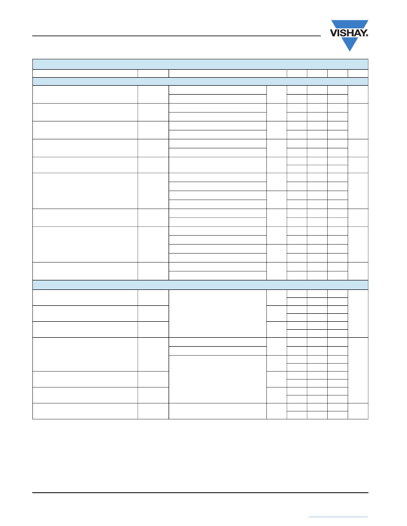
�SPECIFICATIONS� (T� J� =� 25� °C,� unless� otherwise� noted)�
�Parameter�
�Symbol�
�Test� Conditions�
�Min.�
�Typ.�
�Max.�
�Unit�
�Static�
�Drain-Source� Breakdown� Voltage�
�V� DS� Temperature� Coefficient�
�V� GS(th)� Temperature� Coefficient�
�V� DS�
�?� V� DS� /T� J�
�?� V� GS(th)� /T� J�
�V� GS� =� 0� V,� I� D� =� 250� μA�
�V� GS� =� 0� V,� I� D� =� 250� μA�
�I� D� =� 250� μA�
�I� D� =� 250� μA�
�I� D� =� 250� μA�
�I� D� =� 250� μA�
�Ch-1�
�Ch-2�
�Ch-1�
�Ch-2�
�Ch-1�
�Ch-2�
�20�
�20�
�19�
�20�
�-� 4.8�
�-� 5.3�
�V�
�mV/°C�
�Gate� Threshold� Voltage�
�Gate� Source� Leakage�
�V� GS(th)�
�I� GSS�
�V� DS� =� V� GS� ,� I� D� =� 250� μA�
�V� DS� =� V� GS� ,� I� D� =� 250� μA�
�V� DS� =� 0� V,� V� GS� =� ±� 20� V�
�Ch-1�
�Ch-2�
�Ch-1�
�Ch-2�
�1�
�1�
�2.2�
�2.2�
�±� 100�
�±� 100�
�V�
�nA�
�V� DS� =� 20� V,� V� GS� =� 0� V�
�Ch-1�
�1�
�Zero� Gate� Voltage� Drain� Current�
�I� DSS�
�V� DS� =� 20� V,� V� GS� =� 0� V�
�V� DS� =� 20� V,� V� GS� =� 0� V,� T� J� =� 55� °C�
�Ch-2�
�Ch-1�
�1�
�5�
�μA�
�V� DS� =� 20� V,� V� GS� =� 0� V,� T� J� =� 55� °C�
�Ch-2�
�5�
�On-State� Drain� Current� b�
�I� D(on)�
�V� DS� ??� 5� V,� V� GS� =� 10� V�
�V� DS� ??� 5� V,� V� GS� =� 10� V�
�Ch-1�
�Ch-2�
�15�
�20�
�A�
�V� GS� =� 10� V,� I� D� =� 19� A�
�Ch-1�
�0.0055� 0.0068�
�Drain-Source� On-State� Resistance� b�
�R� DS(on)�
�V� GS� =� 10� V,� I� D� =� 20� A�
�V� GS� =� 4.5� V,� I� D� =� 16.5� A�
�Ch-2�
�Ch-1�
�0.0027� 0.0033�
�0.0072� 0.0090�
�?�
�V� GS� =� 4.5� V,� I� D� =� 20� A�
�Ch-2�
�0.0034� 0.0043�
�Forward� Transconductance� b�
�g� fs�
�V� DS� =� 10� V,� I� D� =� 19� A�
�V� DS� =� 10� V,� I� D� =� 20� A�
�Ch-1�
�Ch-2�
�45�
�85�
�S�
�Dynamic� a�
�Input� Capacitance�
�Output� Capacitance�
�Reverse� Transfer� Capacitance�
�Total� Gate� Charge�
�C� iss�
�C� oss�
�C� rss�
�Q� g�
�Channel-1�
�V� DS� =� 10� V,� V� GS� =� 0� V,� f� =� 1� MHz�
�Channel-2�
�V� DS� =� 10� V,� V� GS� =� 0� V,� f� =� 1� MHz�
�V� DS� =� 10� V,� V� GS� =� 10� V,� I� D� =� 19� A�
�V� DS� =� 10� V,� V� GS� =� 10� V,� I� D� =� 20� A�
�Ch-1�
�Ch-2�
�Ch-1�
�Ch-2�
�Ch-1�
�Ch-2�
�Ch-1�
�Ch-2�
�Ch-1�
�820�
�2310�
�290�
�730�
�115�
�305�
�11.5�
�38�
�6.9�
�18�
�60�
�11�
�pF�
�Gate-Source� Charge�
�Gate-Drain� Charge�
�Q� gs�
�Q� gd�
�Channel-1�
�V� DS� =� 10� V,� V� GS� =� 4.5� V,� I� D� =� 16.8� A�
�Channel-2�
�V� DS� =� 10� V,� V� GS� =� 4.5� V,� I� D� =� 20� A�
�Ch-2�
�Ch-1�
�Ch-2�
�Ch-1�
�Ch-2�
�18.2�
�2.4�
�6.6�
�1.7�
�4.8�
�28�
�nC�
�Gate� Resistance�
�R� g�
�f� =� 1� MHz�
�Ch-1�
�Ch-2�
�0.3�
�0.2�
�1.3�
�0.8�
�2.6�
�1.6�
�?�
�Notes:�
�a.� Guaranteed� by� design,� not� subject� to� production� testing.�
�b.� Pulse� test;� pulse� width� ?� 300� μs,� duty� cycle� ?� 2� %.�
�www.vishay.com�
�2�
�Document� Number:� 65733�
�S11-2379-Rev.� B,� 28-Nov-11�
�This� document� is� subject� to� change� without� notice.�
�THE� PRODUCTS� DESCRIBED� HEREIN� AND� THIS� DOCUMENT� ARE� SUBJECT� TO� SPECIFIC� DISCLAIMERS,� SET� FORTH� AT� www.vishay.com/doc?91000�
�发布紧急采购,3分钟左右您将得到回复。
相关PDF资料
SIZ720DT-T1-GE3
MOSFET N-CH D-S 20V POWERPAIR
SIZ902DT-T1-GE3
MOSFET N-CH 30V DUAL D-S
SKY12322-86LF-EVB
BOARD EVALUATION FOR SKY12322-86
SKY12323-303LF-EVB
BOARD EVALUATION FOR SKY1232-303
SKY12324-73LF-EVB
BOARD EVALUATION FOR SKY12324-73
SKY12325-350LF-EVB
BOARD EVAL FOR SKY12325-350
SKY12328-350LF-EVB
BOARD EVAL FOR SKY12328-350
SKY12339-350LF-EVB
BOARD EVAL FOR SKY12339-350
相关代理商/技术参数
SIZ720DT-T1-GE3
功能描述:MOSFET N-CH D-S 20V POWERPAIR RoHS:是 类别:分离式半导体产品 >> FET - 阵列 系列:TrenchFET® 产品目录绘图:8-SOIC Mosfet Package 标准包装:1 系列:- FET 型:2 个 N 沟道(双) FET 特点:逻辑电平门 漏极至源极电压(Vdss):60V 电流 - 连续漏极(Id) @ 25° C:3A 开态Rds(最大)@ Id, Vgs @ 25° C:75 毫欧 @ 4.6A,10V Id 时的 Vgs(th)(最大):3V @ 250µA 闸电荷(Qg) @ Vgs:20nC @ 10V 输入电容 (Ciss) @ Vds:- 功率 - 最大:1.4W 安装类型:表面贴装 封装/外壳:PowerPAK? SO-8 供应商设备封装:PowerPAK? SO-8 包装:Digi-Reel® 产品目录页面:1664 (CN2011-ZH PDF) 其它名称:SI7948DP-T1-GE3DKR
SIZ728DT
制造商:VISHAY 制造商全称:Vishay Siliconix 功能描述:N-Channel 25 V (D-S) MOSFETs
SIZ728DT_12
制造商:VISHAY 制造商全称:Vishay Siliconix 功能描述:N-Channel 25 V (D-S) MOSFETs
SIZ728DT-T1-GE3
功能描述:MOSFET 25V 16A / 35A N-Ch MOSFET
RoHS:否 制造商:STMicroelectronics 晶体管极性:N-Channel 汲极/源极击穿电压:650 V 闸/源击穿电压:25 V 漏极连续电流:130 A 电阻汲极/源极 RDS(导通):0.014 Ohms 配置:Single 最大工作温度: 安装风格:Through Hole 封装 / 箱体:Max247 封装:Tube
SIZ730DT
制造商:VISHAY 制造商全称:Vishay Siliconix 功能描述:N-Channel 30 V (D-S) MOSFETs
SIZ730DT_12
制造商:VISHAY 制造商全称:Vishay Siliconix 功能描述:N-Channel 30 V (D-S) MOSFETs
SiZ730DT-T1-GE3
功能描述:MOSFET 30V 16/35A 27/48W 9.3/3.9mohm @ 10V
RoHS:否 制造商:STMicroelectronics 晶体管极性:N-Channel 汲极/源极击穿电压:650 V 闸/源击穿电压:25 V 漏极连续电流:130 A 电阻汲极/源极 RDS(导通):0.014 Ohms 配置:Single 最大工作温度: 安装风格:Through Hole 封装 / 箱体:Max247 封装:Tube
SIZ790DT
制造商:VISHAY 制造商全称:Vishay Siliconix 功能描述:Dual N-Channel 30 V (D-S) MOSFETs with Schottky Diode